How to Remove the Back of an Hp Pavilion Smart Touch Laptop
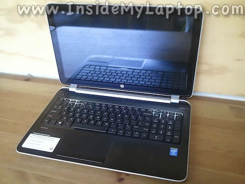
In this guide I explain how to disassemble a HP Pavilion TouchSmart 15.
For this example I'm taking apart a HP Pavilion 15-n280us model.
Make sure the notebook is turned off before the disassembly process.
STEP 1.
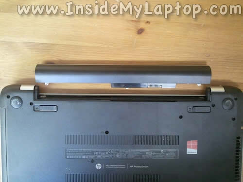
Unlock and remove and replace the battery if necessary.
STEP 2.
Loosen two screws securing the RAM/wireless card cover.

STEP 3.
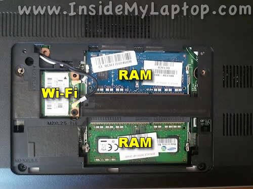
Using a plastic stick pry the cover out and remove it.

Under the cover you can access both RAM modules and wireless card.
We'll be removing the wireless card and one of the RAM modules after step 27 in order to remove the motherboard.
This laptop supports up to 16GB (2x8GB) DDR3-12800 SODIMM RAM modules.
STEP 4.
Remove one screw securing the optical drive.

STEP 5.
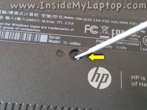
I had some trouble removing the optical drive from the case so I used the following technique.
Using a small screwdriver push the optical drive out through the screw hole.
The drive will move to the left a little bit.
STEP 6.
Now you can pull the optical drive out and remove it.

STEP 7.
Remove one screw securing the keyboard.

STEP 8.
To remove the keyboard do the following.
Place the notebook on its side.
Push on the back side of the keyboard with a small screwdriver thought the screw hole.
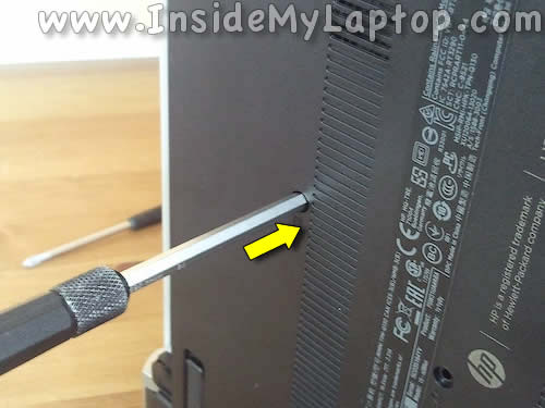
STEP 9.
While pushing on the back, you will see the front side separated from the top cover a little bit.
Insert your fingers under the keyboard.
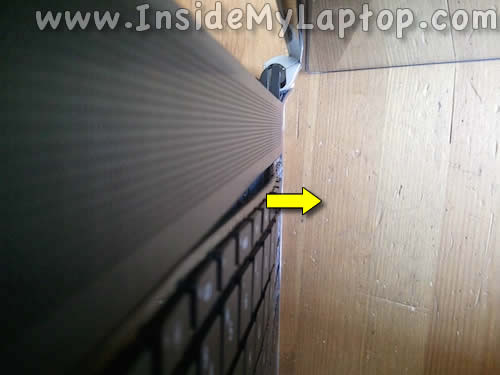
STEP 10.
Continue separating the keyboard from the top cover.
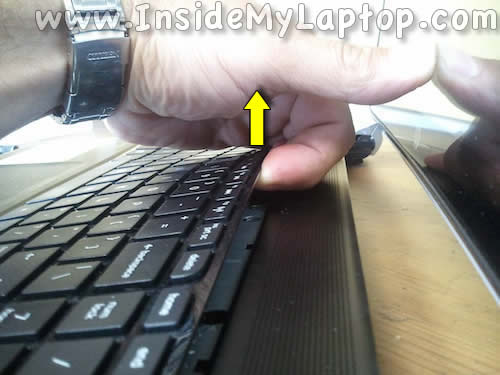
STEP 11.
Turn the keyboard upside down and place it on the palm rest.

STEP 12.
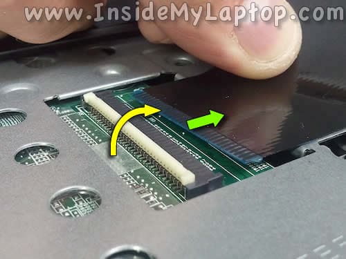
Now you can access the cable and disconnect it from the motherboard.
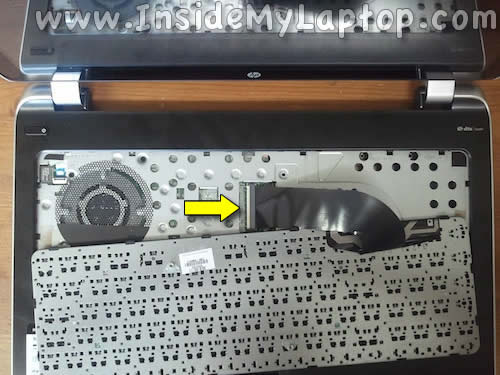
STEP 13.
Unplug the keyboard cable in two steps:
1. Lift up the retaining tab – white piece in my example (yellow arrow).
2. Pull the cable out of the connector (green arrow).
STEP 14.
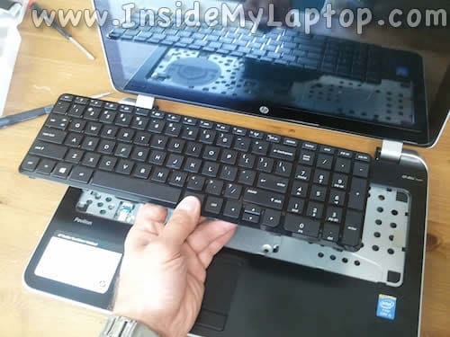
Remove the keyboard completely. New replacement keyboards available here.
STEP 15.
Remove all screws from the bottom cover.

STEP 16.
Remove three more screws from the optical drive bay.

STEP 17.
Remove screws securing the top cover assembly.
Disconnect the power button cable (yellow arrow) and touchpad cable (green arrow).
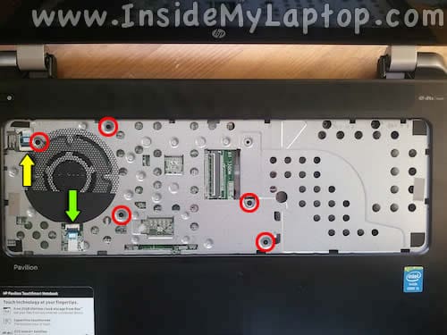
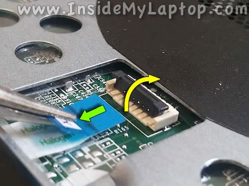
Here's how to disconnect both cables.
Unlock the connector and pull the cable out.
STEP 18.
Start separating the top cover from the bottom case using a plastic stick or any other similar tool.
Begin in the display hinge area.

STEP 19.
Continue removing the top cover.
You can use a guitar pick to separate two parts.
Insert it under the top cover and move slowly along the side to unlock hidden latches.
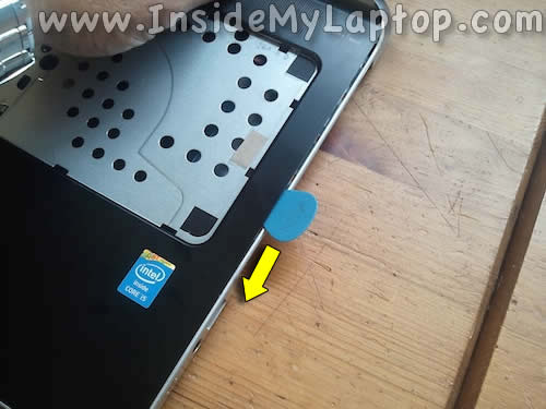
STEP 20.
Remove the top cover (palm rest) assembly.
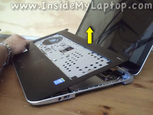
STEP 21.
On the bottom side of the top cover you can access the power button board, touchpad and touchpad button board.

STEP 22.
In order to access and remove the hard drive you'll have to disconnect and remove the USB/audio board first.
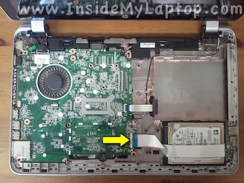
STEP 23.
Disconnect the USB/audio board cable.
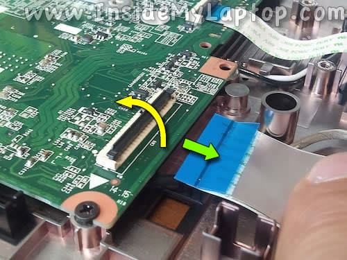
STEP 24.
Remove one screw securing the board.
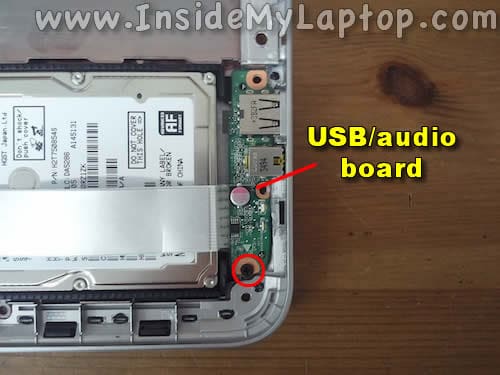
STEP 25.
Lift up and remove the board.

STEP 26.
Lift up the hard drive from the case and disconnect the SATA cable.
Now you can replace the hard drive with a new one if necessary.
I recommend replacing this regular 2.5″ SATA hard drive to a 2.5″ SATA solid state drive. Doing so will improve the laptop performance significantly.

STEP 27.
In order to remove the motherboard it's necessary to disconnect and remove the wireless card first.
Unplug both antenna cables and remove one screw securing the card.
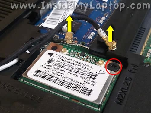
STEP 28.
Pull the wireless card out.
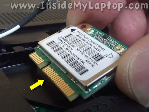
STEP 29.
Also, it's necessary to remove one of the RAM modules.
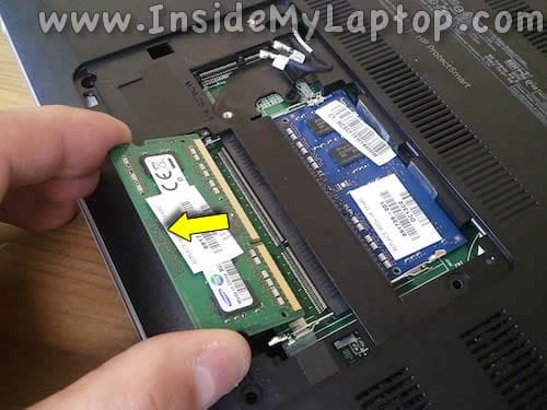
STEP 30.
Disconnect four cables.
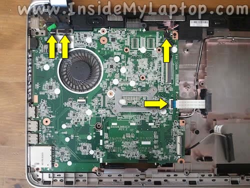
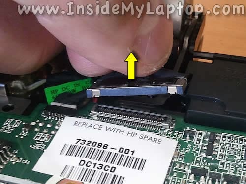
Unplug the display cable by lifting it up by the black tab on the top.
Disconnect the webcam cable located on the left from the display connector.

Disconnect the speaker cable.

Unlock and disconnect the optical drive connector cable.

STEP 31.
Remove two screws from the bracket securing the power connector (DC jack).

STEP 32.
Remove the bracket.

STEP 33.
Separate the power connector from the case and lift it up.
You can disconnect it completely only when the motherboard removed.

STEP 34.
Remove all screws securing the motherboard.

STEP 35.
Start removing the motherboard on the right side as it shown on the following picture.
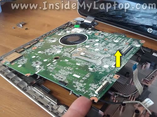
STEP 36.
Remove it from the case completely.

STEP 37.
On the other side of the motherboard you can access the CMOS battery.

STEP 38.
Now you can unplug the DC jack.

STEP 39.
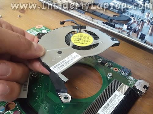
Remove two screws securing the cooling fan.
Unplug the fan cable.
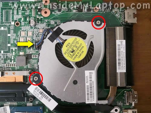
STEP40.
Lift up and remove the fan.
How to Remove the Back of an Hp Pavilion Smart Touch Laptop
Source: https://www.insidemylaptop.com/how-to-disassemble-hp-pavilion-touchsmart-15/
0 Response to "How to Remove the Back of an Hp Pavilion Smart Touch Laptop"
Post a Comment